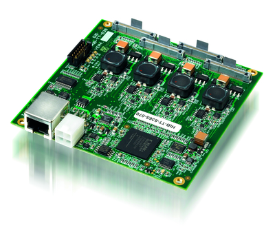
Head interface board
Ever wondered what tells an inkjet printhead how to turn images into ink drops on the paper? Simon Eccles visits Global Inkjet Systems to find out.
How do inkjet print jobs go from images on a screen to drops of ink projected from rows of nozzles? And how does an inkjet printer organise how all those drops build up an image? It is not straightforward, given that there are usually multiple printheads and in the case of a scanning printer with a left-right moving head carriage, there is usually a user choice of whether to run a lot of overlapping passes to build up a high quality image at the expense of speed, or to run minimum passes in the interests of speed, but with a lower quality final printed appearance.
It is all done by the RIP, right? Well, not exactly. When we started to ask that question when researching the story on inkjet printheads (Digital Printer September 2013), it turned out that there is a stage that is rarely considered and almost never explained. The printhead control system bridges the gaps between the software input (ie the RIP) and the mechanical output (the printhead that fires ink drops). Building that link is a specialist task that is often outsourced by the printer makers. This is not unusual: many printer manufacturers buy in printheads rather than make their own.
However, the printhead makers often supply GIS is located in modern offices in the St John Innovation Park in Cambridge. Nick Geddes, CEO of Global Inkjet Systems the electronics to drive them. It makes sense to go to a specialist to build these. So we visited a specialist to ask how it is done.
Cambridge controllers
Global Inkjet Systems in Cambridge was set up in 2006 specifically to develop inkjet controllers. It makes hardware, firmware and software that it supplies in complete packages to printer builders, ink manufacturers and integrators.
Its systems drive printheads from the likes of Fujifilm Dimatix, Konica Minolta, Kyocera, Ricoh, Toshiba Tec and Xaar, between 30 and 40 models in total.
Nick Geddes, the chief executive officer and major shareholder, set the company up together with Jim Brotton. Today the company employs 32 people and occupies part of a modern office block in an innovation park on the outskirts of Cambridge.
Last year it won a Queen’s Award for Enterprise, covering International trade. Some 89% of its total sales in 2012 were in international markets – an increase from 47% in 2010. Overseas sales growth was 132% in 2012.
All of GIS’ customers are OEMs, as the integration work means there is no scope for selling to end users even if the company wanted to. It also means that Mr Geddes cannot name his customers, though he said that most of them are in the high end graphics or industrial sector, making both single-pass and multipass (scanning-head) printers.
Applications are a mix of graphical and non-graphical: textiles, label printing, wide format, coding and marking, mailing, product decoration, packaging, ceramic tiles, glass, laminates, security printing and materials deposition (the latter including 3D, spot varnishing and the like). ‘We don’t do mass market solvent printers,’ said Mr Geddes. ‘There’s not much margin in these, so people don’t tend to come to us for solutions.’
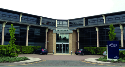 GIS is located in modern offices in the St John Innovation Park in Cambridge
Hardware and firmware
Several GIS hardware, firmware and software systems link together to form a customised control system for each type of printhead it supports. It calls this the uniti operating system, which is a mix of user interface, print server, RIP, software, printer drivers and electronics.
‘We start with the printhead that the customer has selected,’ Mr Geddes explained. ‘We add the GIS head personality interface boards, specific to the head. We use FPGA (Field Programmable Gate Array) processors, which are blank programmable boards where ewe can set pin-outs to the head.
‘Then we add the Print Management board. This is a gatekeeper that synchronises all the data with an encoder that tells the heads to fire. This is in sync with the printer speeding up or slowing down. Our GIS operating system is used to set up the voltages, waveforms and to stream data from the RIP to the hardware in the correct data format.’
There is a huge variation in printer heads and their configurations, Mr Geddes pointed out. Apart from the number of heads in a particular printer, their arrangement can vary (for instance staggered and overlapped or mechanically butted in a straight line). The number of nozzles varies, as do the pitch and alignment that determine the native resolution of the head (many heads have two rows of nozzles, staggered).
 Nick Geddes, chief executive officer and major shareholder
Drop ordering
Organising the image data into ink droplets is the really clever part, that is set up through the GIS user interface by the OEM. In the simplest case, the image is split up into stripes, with each stripe representing a line along which the line of nozzles can either fire or not fire droplets. So the controller passes a row of binary 1 or 0 signals to all the nozzles, telling them whether to fire or not.
With a head that has two staggered rows of nozzles, then you print two stripes at once, but each only addresses half the possible positions, so it takes two firing stripes to build up one whole row, with the media or head moving in between. The controller has to work out which of the nozzles to fire in each sequence. For multi-pass heads it gets ever more complicated.
Here you have not only got the stripes to consider, but the overlaps. As the media advances, the heads create swathes of print, which overlap slightly to build up the full image density over multiple passes. The smaller the media advance, the smaller the overlap, therefore the greater number of times the nozzles will pass over a given area of print and the higher the image resolution you get.
The printhead control system has to be told how to split up the total image into both stripes and passes (which in turn can be bidirectional or unidirectional), to build up the whole image. Visible banding can be reduced by the controller feathering the edges of swathes in a scalloped pattern.
The staggered nozzles and the overlapping swathes help to conceal any blocked nozzles, but there are additional refinements possible such as waiting until the media has advanced half a head’s width before printing the second row of a staggered nozzle pattern. It is also possible to semi-randomise the nozzle firing order across a group of overlapping swathes.
All of these techniques are available to OEMs, who then apply their own knowledge to suit their particular printers and inks. ‘There are probably as many different implementations as there are printers,’ said Mr Geddes. ‘Two printer manufacturers with our stuff and the same heads may have completely different interleaving strategies.’
Specialised RIPs
Although the GIS systems can be used with third party RIPs, the company has developed a pair of its own RIPs, as well as a user interface, colour management, layout software and an automatic mask generator (for white ink, spot varnish layers etc). Sometimes the dedicated RIPs are needed to handle the particular requirements of complex drop control.
If you are not a printer manufacturer, chances are you will never have heard of these RIPs, even if they are supplied with a printer you are using. The OEMs integrate them with their own software and often put their own user interface on top.
One of these is a high speed PDF RIP, though PDF is not a big requirement in the sort of work the OEM printers are used for. The other is a high speed variable data RIP that can take information from a database and if necessary call up images from another disk. Barcodes and the like can be generated on the fly.
Mr Geddes claims that it is the only live variable data RIP in its class that he is aware of. This can be used to generate live barcodes and similar variables on the fly, in response to triggering systems on a production line, such as a camera vision system.
The variable data RIP cannot render PDFs, so if this is a requirement a Harlequin RIP can be integrated, outputting greyscale bitmaps (normally of static artwork elements) to the GIS RIP, which then integrates them with any variable elements, applies screening and separations and passes the lot downstream to the print management board.
GIS can also control more than one head type in the same printer, which adds anotherlayer of complexity. ‘Typically this will be a different type for white or clear for large particles, with small particles for CMYK,’ said Mr Geddes.
‘Alternatively there might be very high resolution black and standard CMY. Or a pre-coating fluid in garment printing. These can be heads from different manufacturers if needed. We can cope with asymmetric resolutions and different resolutions for each colour channel. This would be invisible to the user.’
Conical conundrum
Another fiendishly complex problem is conical-section objects (think paper cups or ice cream tubs). These can be aligned with the long edge parallel to the head, but this means that the wide and narrow ends move by a different distance for every degree of rotation. This means that the drop density and the resolution of the print varies continuously along the length. ‘Normal screening doesn’t work, and you get graininess that looks horrible, said Mr Geddes. ‘Then there’s dot gain. Colour calibrating with greyscale is a nightmare.
We correct for all those effects, so all that’s left is the distortion. We’ve only done it for a small number of heads so far but we can do it for any. It’s imperfect but you can get quite a long way towards making something look pretty good.’
